How are 3D anatomy models made? A CT or MRI scan is exported as DICOM slices, structures are segmented into masks, the masks are converted to a surface mesh, and the mesh is cleaned and exported for viewing or printing.
The result depends on scan quality and on how carefully each structure is outlined. This guide follows one model through each stage. For the wider picture, see the overview of the 3D human anatomy model.
The workflow at a glance
Every anatomical model built from patient imaging passes through the same five stages. Each stage changes the data format, so knowing the format tells you where a project currently stands.
| Stage | Data in hand | Planning use |
|---|---|---|
| Acquisition | CT or MRI slices stored as DICOM | Scan quality fixes the ceiling for model detail, so check resolution and contrast first. |
| Preparation | DICOM converted to an image stack such as TIFF | Needed when a segmentation tool cannot read DICOM directly. |
| Segmentation | Labelled masks, one label per structure | The slowest, most judgement-heavy stage; budget the most review time here. |
| Meshing and cleanup | Polygon surface for each label | Cleanup decides whether the model is fit for viewing or printing. |
| Export | A mesh file in a format the end use accepts | Pick the format from the destination, whether a viewer, game engine or printer. |
Stage descriptions draw on the PostDICOM explanation of DICOM data and the Galaxy Training Network DICOM anatomical 3D workflow.
Starting with the scan: CT, MRI and DICOM
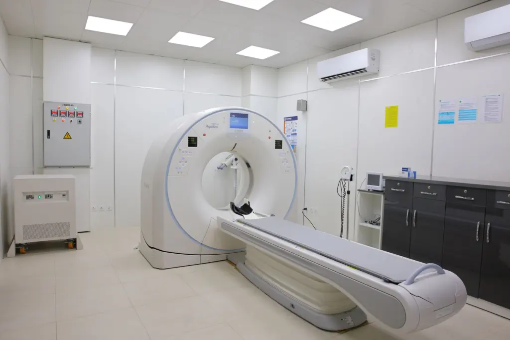
A DICOM data set is the raw material of the whole process. CT and MRI scanners are among the acquisition devices the standard covers, according to the overview of the DICOM standard in the medical informatics literature.
That overview describes DICOM as a message standard, a specification for exchanging information between computer systems. It sets out a non-proprietary data interchange protocol, a digital image format and a file structure for biomedical images. At the time of that description, the standard ran to a thirteen-volume set (1997), so it is far larger than a simple image format.
What a DICOM file contains
According to PostDICOM, any DICOM medical image has two parts: a header and the image itself. The header can carry image characteristics such as acquisition parameters, pixel intensity and matrix size. Modelling software reads that information to place each slice correctly in space.
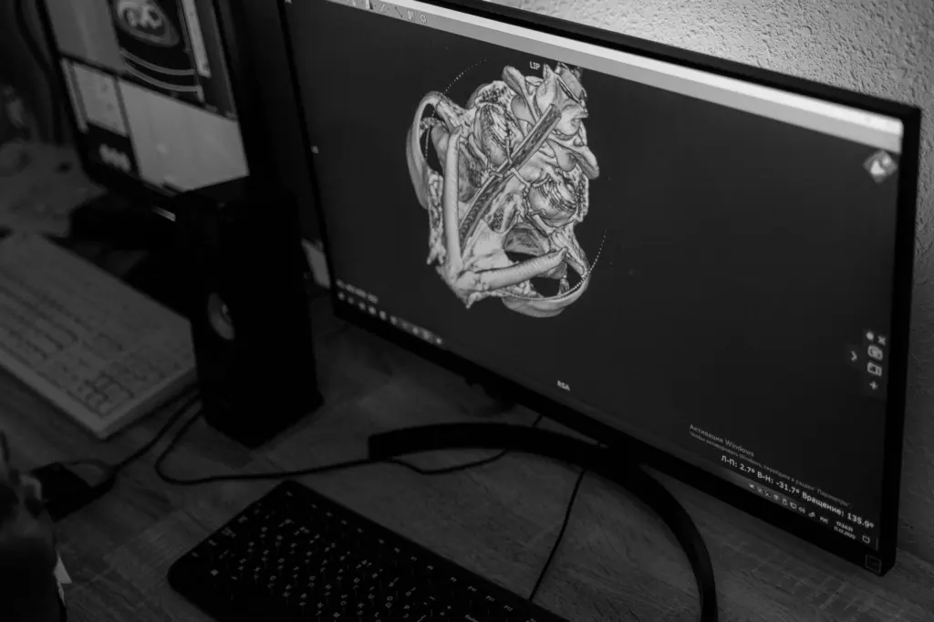
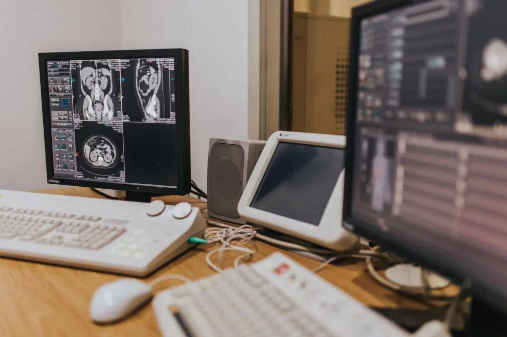
The initial data set is a series of two-dimensional images taken in the axial, coronal and sagittal planes. Those images can be reconstructed into a three-dimensional view of the anatomical area.
Opening DICOM data
Regular imaging software on an operating system cannot open DICOM medical imaging data. A dedicated DICOM viewer or a medical imaging tool is required, and that need shapes the choice of software for later stages. Readers comparing options can start with the guide to the best free 3d human anatomy software.
Patient identifiers also sit in the headers. Keylabs notes that in shared training data, personal data in DICOM headers is removed or replaced with random identifiers. Any model built for teaching should start from data treated this way.
Segmentation: turning slices into labelled structures
Segmentation is the process of marking which pixels in each slice belong to which structure, such as a bone, an organ or a vessel. It is needed because a scan only stores intensity values, so the computer cannot tell a rib from the tissue next to it without outlines.
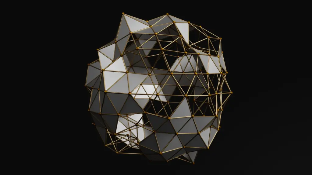
Keylabs explains that medical images are never just flat 2D pictures but a set of slices forming a 3D volume. Experts mark structures slice by slice on the 2D images, and those markings are then assembled into a 3D mask. The outlines can be drawn manually or semi-automatically on each slice.
A documented software workflow
The Galaxy Training Network publishes a DICOM anatomical 3D workflow that shows how the stage can be scripted. Its steps include converting DICOM to TIFF with highdicom_dicom2tiff and applying an automatic threshold. They also include a ridge filter and a conversion of binary images to label maps.
Thresholding separates bright structures such as bone from darker background. The label map then gives each separated region its own identity. Manual review follows, because automatic thresholds alone rarely isolate neighbouring structures with similar intensity.
Meshing and cleanup
Meshing converts the 3D mask into a polygon surface that graphics software and printers can use. A mask is a block of labelled voxels, while a mesh is a skin of connected polygons wrapped around the boundary of each label.
Cleanup is the stage where a rough surface becomes a usable model. Smoothing, repairing holes and removing stray fragments are standard jobs, and teams usually do them in general 3D modelling or sculpting programs. In one vendor project documented by Body Scientific, 3D software and sculpting programs were used to sculpt the shape of a head model. Sculpting suits teaching models, where clarity matters more than reproducing every voxel.
Keep the segmented mask even after the mesh is finished. If a structure needs correcting later, editing the mask and re-meshing is safer than patching the mesh by hand.
Export and physical output
The finished mesh is exported in a format matched to its use. Viewers, learning platforms and printers each accept different files, and the guide to 3d anatomy model file formats compares them. In the workflow itself, DICOM is the input format and an intermediate image stack such as TIFF is common. The export format is chosen last.
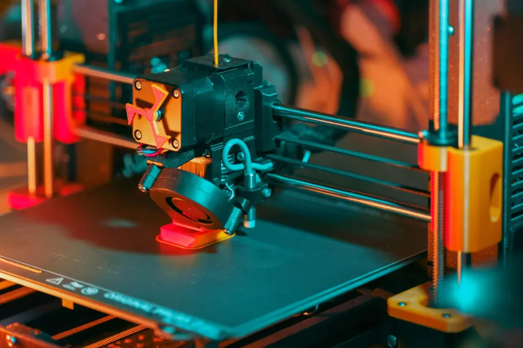
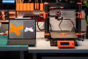
Printing is one of the main physical outputs. Body Scientific describes a project that moved from 3D modelling to 3D printing, using the sanded and smoothed print as a master to cast and mold the shape of the head. A print can therefore serve as a finished model or as a pattern for producing copies.
Time and accuracy limits
No single duration applies to every model. Body Scientific reports taking one custom anatomy project from a pencil sketch concept to a final product within only a few months. That figure covers sculpting, printing and casting, not a quick scan-to-mesh conversion, so use it as a sense of scale rather than a quote. Time rises with the number of structures, the amount of manual outlining and the cleanup a surface needs.
Accuracy is limited first by the scan. Keylabs notes that scans from different devices differ in quality, resolution and contrast, which affects how clearly boundaries can be drawn. Fine detail that never reached the scan cannot be recovered during segmentation or meshing.
Accuracy is limited second by the person or algorithm outlining each slice. Manual and semi-automatic outlining involve judgement at soft boundaries, and two operators can produce slightly different masks. Treat teaching models as faithful representations of one scan, not as measurements, unless the project includes a documented check against the original data.
Frequently asked questions
Can an ordinary image viewer open the scan files?
No. PostDICOM states that regular imaging software on an operating system cannot open DICOM data, so a dedicated DICOM viewer is needed.
Does MRI work as well as CT for building a model?
Both can supply the slices. The DICOM standard covers CT and MRI acquisition equipment, so either can enter the same pipeline, though the choice affects which structures show clearly.
Do models carry patient information?
They should not. Patient identifiers sit in DICOM headers, and shared data sets have those details removed or replaced with random identifiers before use.
Why is the scan stored as many images rather than one?
A scan is a set of 2D slices that together form a 3D volume. Reconstructing the slices gives the three-dimensional view that segmentation and meshing build on.