| Phase | Supported detail | Planning use |
|---|---|---|
| Imaging data | 3D Slicer and InVesalius import MRI and CT scan data in DICOM format | Request DICOM from the imaging source, not screenshots or exported pictures, so reconstruction starts from the original slices. |
| Reconstruction software | InVesalius is open source software for reconstructing CT and MRI images | An open source tool lets a team test the segmentation step before committing to a commercial pipeline. |
| Labeling standard | FDA recognized ASTM F2943-25 (end user labeling for musculoskeletal implants) on December 22, 2025 | Build labeling content against the current standard from the start of the design file. |
| Transition period | Declarations of conformity to the earlier ASTM F2943-14 recognition are accepted until December 19, 2027 | Treat the earlier version as a short-term allowance, not a design target. |
The table draws on the UT Health San Antonio library guide for the imaging rows and on the FDA recognized consensus standards entry for the labeling rows.
3D anatomy models for implant design start as CT or MRI data in DICOM format, become cleaned meshes, and only then become solid CAD geometry that can be dimensioned and checked.
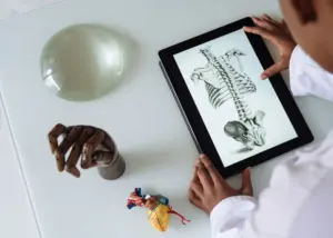
Readers who need background on what a 3D human anatomy model is and where such models come from can start with the hub guide. This page covers the narrower engineering path from scan to implant geometry, and the regulatory limits that sit around it.
Imaging data: CT scan and DICOM
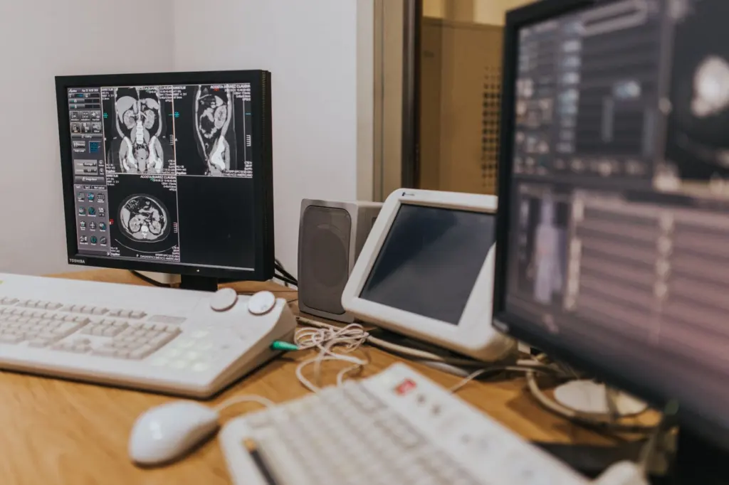
An implant-grade bone model begins with a CT scan, and the DICOM file set is the correct starting format. The UT Health San Antonio library guide notes that programs such as 3D Slicer and InVesalius allow importing of MRI and CT scan data in DICOM format, which makes DICOM the common entry point for reconstruction.
For bone, CT is the usual choice of source. MRI can be imported by the same programs, so the decision depends on what the imaging source already holds for the patient or specimen. Whichever modality is used, keep the original DICOM series unchanged and work on copies, so every later surface can be traced back to the slices it came from.
Segmentation and mesh preparation
Segmentation converts grayscale slices into a labeled bone region, and its quality sets the ceiling for everything downstream. InVesalius, described by the same library guide as open source software for reconstruction of computed tomography and MRI images, is a practical place to learn this step without licence cost. 3D Slicer covers the same DICOM import task.
Work through the stage in this order:
- Load the full DICOM series. Confirm the slice order and orientation before doing anything else.
- Isolate the bone. Separate the target bone from neighbouring structures and check the result slice by slice, not only in the 3D view.
- Generate the surface mesh. Export it in a mesh format the CAD package accepts.
- Inspect the mesh. Look for holes, spikes and merged joints, and repair them at the segmentation stage where possible.
Fixing errors in the segmentation is better than patching the surface later, because a patched mesh no longer matches the scan it claims to represent.
From mesh to solid in CAD
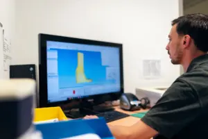
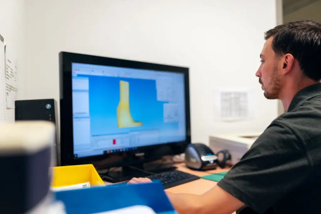
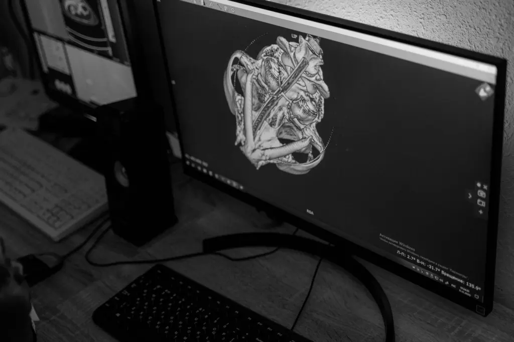
Turning a 3D bone model into CAD geometry means converting a faceted surface into surfaces and solids that a designer can dimension, cut and offset. In a package such as SolidWorks, the imported bone mesh serves mainly as a reference body. The designer builds clean surfaces or sketches over it, then creates solid features from those.
Choosing how much of the bone to convert
Convert only the region the implant touches. A full bone converted to a solid is heavy to edit and rarely needed. A local patch around the contact area, or a few well-chosen cross-sections, is usually enough to control fit and keeps the file responsive.
Keeping the mesh and the solid linked
Keep the original mesh in the assembly beside the new solid and compare them regularly. This gives a visible deviation check at each design change, and it keeps the scan-derived geometry separate from design intent.
A model prepared for animation is a different product. The workflow described in 3d human anatomy for animation tolerates surface approximations that look right on screen, whereas implant work needs geometry that can be measured and defended.
Designing the orthopedic implant against the anatomy
An orthopedic implant is designed against the bone surface, so the CAD model should hold both bodies in one coordinate system. Place the implant in the bone model, then adjust the contact regions until the bone-facing surface follows the anatomy where the design requires it.
Record the reasoning behind each design choice in the file or the design record. Regulators and reviewers look for risk-based reasoning. The FDA standards entry states that orthopedic implant label content should be influenced by risk management, which is a reminder that design decisions and information supplied with the device belong to one controlled process.
Physical models for fit checking
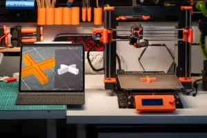
A printed bone model gives a quick, tangible check of how the implant sits, and it catches problems that are easy to miss on screen. Print the bone region and the implant together, then test seating and clearances by hand. The printing side of this work is covered in 3d printing human anatomy models.
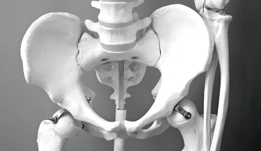
A printed part is only a stand-in for the CAD model, so its usefulness depends on whether it matches the digital dimensions.
Dimensional verification
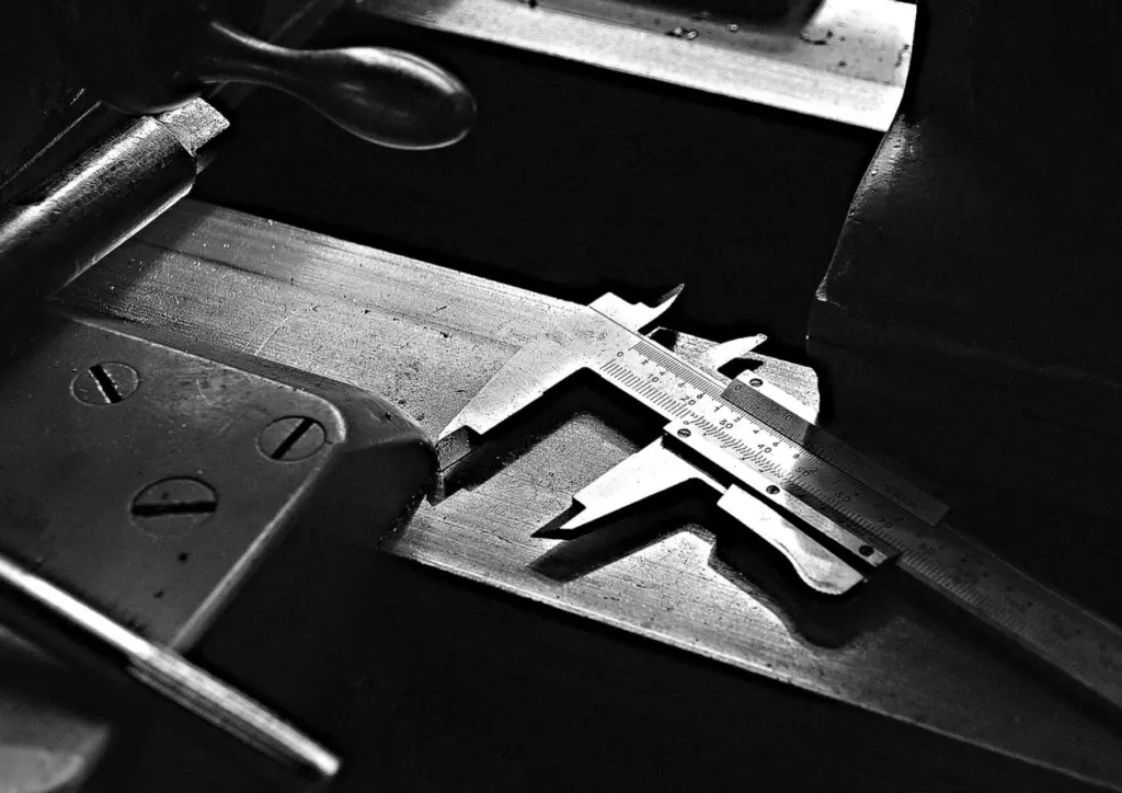
Measure the printed bone with calipers at the features that control fit, and compare readings with the same dimensions in CAD. If the printed part differs from the file, resolve that before judging the implant design, since a printing error and a design error look alike on the bench.
Regulatory limits for patient-matched implants
Patient-matched implants are regulated medical devices, and a model that works in CAD is not evidence that a device may be marketed or used. FDA lists consensus standards that manufacturers can cite, and the FDA entry for ASTM F2943-25 shows recognition of that guide for end user labeling of musculoskeletal implants, effective December 22, 2025.
Three practical points follow from that entry:
- Validate label formats. FDA’s entry states that all label formats should be validated, so labeling for an orthopedic implant is part of the design verification plan.
- Mind the transition. FDA will accept declarations of conformity to the prior ASTM F2943-14 recognition until December 19, 2027. Projects that run past that date should move to the current version.
- Use standards as FDA intends. The entry lists FDA guidance on appropriate use of voluntary consensus standards in premarket submissions for medical devices, issued September 2018. It is the reference for how a declaration of conformity fits into a submission.
A recognized standard supports a submission but does not replace it.
Troubleshooting the workflow
- The mesh looks noisy or faceted. Return to segmentation and the imaging data rather than smoothing heavily in CAD, because heavy smoothing moves the surface away from the scan.
- The CAD solid will not form. Check the mesh for holes and self-intersections first, and build solids over a local patch rather than the whole bone.
- The printed model does not match the file. Measure with calipers against the CAD dimensions before changing the design.
- The scan will not import. Confirm that the complete DICOM series was supplied; the supported programs expect DICOM data.
Frequently asked questions
Is there open source software for reconstructing CT scans?
Yes. InVesalius is open source software for reconstructing CT and MRI images, and 3D Slicer also imports DICOM data.
Do implant labels need to be validated?
FDA’s standards entry for ASTM F2943-25 states that all label formats should be validated, and that label content should be influenced by risk management.
Does a recognized FDA standard mean a patient-matched implant is approved?
No. Recognition means FDA accepts a standard for stated purposes, such as end user labeling, and declarations of conformity support a submission. They do not clear the device.
Can an animation-grade bone model be used for implant design?
It can serve as visual reference, but implant work needs geometry traced to the DICOM scan and verified by measurement, which animation models are not built to provide.